An awesome FPGA board with an open source toolchain!
So, I haven’t really writen a blog post since 2017. Since then I’ve started a new job and my primary fun project has been building a 6809-based computer system from scratch and documenting it on my youtube channel. Ok, I think that catches us up.
Anyway, I’m considering using an FPGA as a display processor for the 6809 system, so that it can output text and graphics on a VGA monitor. The Lattice ICE40 devices occupy a sweet spot for FPGA hobbyists because
- they are cheap and reasonably capable
- the amazing IceStorm toolchain lets you program them using entirely open source tools
In this blog post I will document what I did to get an LED blink demo running on the Upduino 3.0 development board using Linux Mint 20, which is based on Ubuntu 20.04. I didn’t find a 100% complete guide to detailing how to do this, so I thought a blog post might be helpful for others who are interested in getting started with this board.
These steps are largely based on a total ripoff of
an Upduino 2.0 tutorial
by Kajetan “Kajtek” Rzepecki.
A few details have changed, which is mainly what I intend to document here.
The Upduino 3.0
The Upduino 3.0 is an inexpensive (around US $20) and breadboard-friendly development board for the ICE40UP5K FPGA. This FPGA has 128 KB of single-port RAM, 15 KB of dual-port block RAM, and sufficient onboard programmable logic to do fairly sophisticated stuff such as RISC-V softcores.
Here’s a picture of the Upduino 3.0 on a breadboard (click to embiggen):
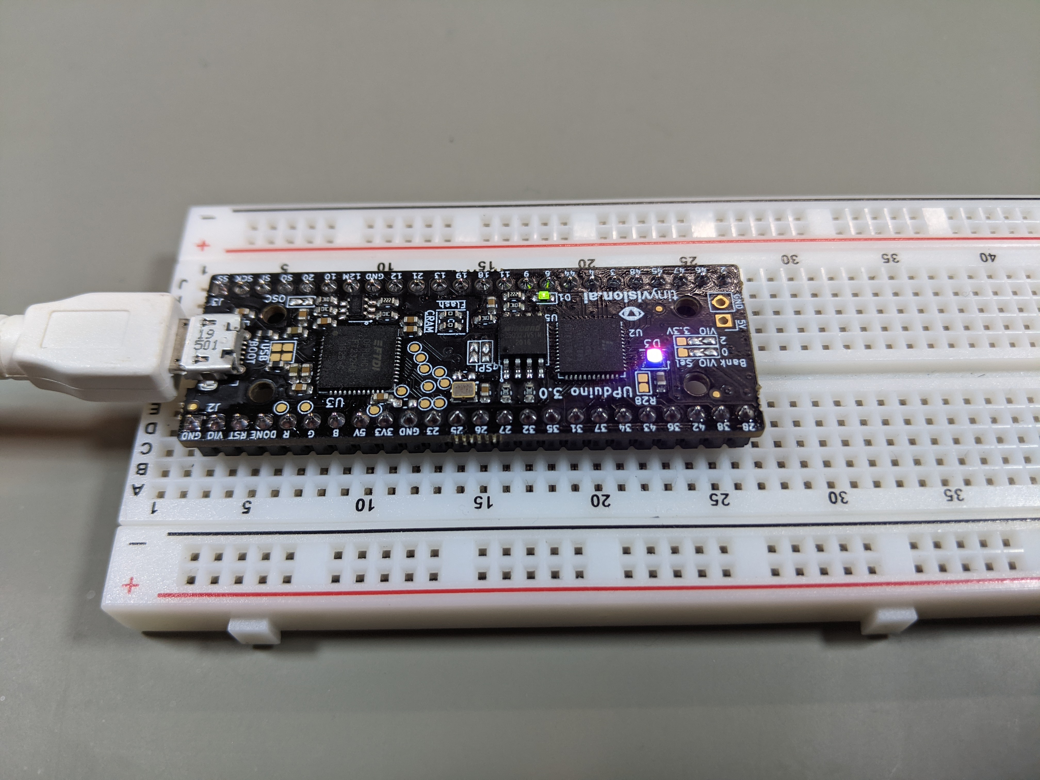
I just noticed that in the picture, it’s upside-down. All of the electrons are going to fall out!
Step 1: software setup
Following the tutorial, I installed the APIO FPGA tools. APIO is essentially a high-level front end that automates the installation of device-specific FPGA tools, synthesis and routing, and uploading the resulting bitstream to the device.
APIO is installed as a Python package using pip. I started by creating a Python3 virtual
environment:
sudo apt-get install python3-venv
python3 -m venv ~/venv
I added the bin directory of the virtual environment to my $PATH:
export PATH=~/venv/bin:$PATH
You’ll probably want to add this to your bash startup scripts so that the
tools in the Python virtual environment are automatically part of your $PATH.
Now install apio:
pip3 install -U apio
Now we can install the APIO packages needed to develop for ICE40 devices:
apio install system ice40 scons iverilog yosys
Update November 2023: on recent versions of apio, you’re better off just
doing
apio install --all
You will need to enable the FTDI drivers:
apio drivers --ftdi-enable
Step 2: make a demo project
This section is a condensed and slightly updated version of Kajtek’s tutorial. (The source code is MIT licensed: see Kajtek’s tutorial for the original versions.)
Create a directory for the project: I created one called blinky in my git directory:
mkdir -p ~/git/blinky
cd ~/git/blinky
Create an apio.ini file:
apio init -b upduino3 -p .
Use a text editor to create a file called up5k.pcf which maps the device pins which
drive the onboard RGB LED, with the following contents:
set_io --warn-no-port led_blue 39
set_io --warn-no-port led_green 40
set_io --warn-no-port led_red 41
Use a text editor to create a Verilog file called blinky.v, with the
following contents:
module blinky (output wire led_blue,
               output wire led_green,
               output wire led_red);

   wire clk;
   SB_HFOSC inthosc(.CLKHFPU(1'b1), .CLKHFEN(1'b1), .CLKHF(clk));

   localparam N = 27;
   reg [N:0] counter;

   always @(posedge clk)
     counter <= counter + 1;

   SB_RGBA_DRV rgb (
     .RGBLEDEN (1'b1),
     .RGB0PWM  (counter[N]),
     .RGB1PWM  (counter[N-1]),
     .RGB2PWM  (counter[N-2]),
     .CURREN   (1'b1),
     .RGB0     (led_blue),
     .RGB1     (led_green),
     .RGB2     (led_red)
   );
   defparam rgb.CURRENT_MODE = "0b1";
   defparam rgb.RGB0_CURRENT = "0b000001";
   defparam rgb.RGB1_CURRENT = "0b000001";
   defparam rgb.RGB2_CURRENT = "0b000001";
endmodule
Step 3: build and program the design
Verify, build, and upload the design to the board (you’ll need to have the board connected via USB):
apio verify
apio build
apio upload
The RGB LED on the board should now be cycling through a pattern of colors.
Conclusions
I have played around with FPGAs a little bit previously, and I have a rudimentary knowledge of Verilog, so my next step is to dive into generating VGA signals and figuring out how to interface the FPGA to the 6809 system. I have a few ideas, and once I have progress to report I’ll share it in some manner (probably a youtube video.) Stay tuned!
blog comments powered by Disqus